imported>Mathieu |
imported>Andy |
| Line 1: |
Line 1: |
| − | [[User:Renato]] at [[Southampton]] is in charge of the [[Parallel Composition using Event-B]].
| + | This Page is Under Construction !!! |
| | | | |
| − | Composition is the process by which it is possible to combine different sub-systems into a larger system. Known and studied in several areas, this has the advantage of reusability and combination of systems especially when it comes to distributed systems. While applying composition, properties must be maintained and proofs obligations need to be discharged in order for the final result to be considered valid. Our goal is to add this feature to the Rodin Platform (using Event-B notation) and study the concerns, properties, conditions, proof obligations, advantages and disadvantages when create/analysing system specifications. Since the composition maintains the monotonicity property of the systems, the sub-systems can be refined independently on a further stage, preserving composition properties.
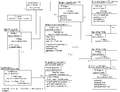
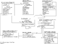
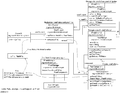
| + | <h1>Entity Relationship Diagrams for the Prover</h1> |
| | | | |
| − | [[Image:share_event_machine.jpeg]]
| + | These diagrams describe the relationships between classes/interfaces - in terms of access to information in related classes. The diagrams are not fully descriptive like a UML class diagram, but contain sufficient information to begin to understand the structural relationships within the RODIN proof tool. The diagrams were produced as an aid to visualising these relationships in order to better understand the structure. |
| | | | |
| − | [[Image:share_event_mach_comp1.jpeg]]
| + | <gallery> |
| − | [[Image:share_event_machine_comp2.jpg]]
| + | Image:ProofStatus.png|Proof Status Diagram |
| − | | + | Image:ProofTree.png|Proof Tree Diagram |
| − | A machine '''''S''''' with events '''''e1, e2, e3''''' and '''''e4''''' and variables '''''v1, v2''''' and '''''v3''''' can be decomposed using event (de)-composition of event ''e2'' (as can be seen above). This would result in the machine '''''S1''''' and '''''S2''''' that have a partial part of the event ''e2'': machine ''S1'' has the part related to the variable ''v1'' (''e2''') and machine ''S2'' has the part related to the machine ''v2'' (''e2''<nowiki>''</nowiki>). Also some other events are separated (''e1'' and ''v1'' only exist on machine ''S1'' and events ''e3'' and ''e4'' with variable ''v3'' only exist on the machine ''S2'') as can be seen above.
| + | Image:UserSupportDiag.png|UserSupport Diagram |
| − | | + | </gallery> |
| − | A document with information about parallel composition using Event-B is available here: [http://eprints.ecs.soton.ac.uk/16907/1/9_months_ecs_template_version.pdf Composition using Event-B Notation.pdf].
| |
| − | | |
| − | A release of the composition plugin for Rodin 0.8.2 is available (email me:ras07r@ecs.soton.ac.uk).
| |
| − | | |
| − | A release for Rodin 0.9 should be available soon (possibly from the main Rodin updates link).
| |
| − | | |
| − | How to use it:
| |
| − | | |
| − | - To install the plug-in, just unpack the context of the zip file ( a folder called 'plugins') into the plugins folder of the Rodin platform. So after this operation, this two files should be seen on the Rodin's plugins folder:
| |
| − | | |
| − | * ac.soton.composition.core_0.0.2.jar
| |
| − | * ac.soton.composition.ui_0.0.2.jar
| |
| − | | |
| − | (''Previous point just applies if not using the main Rodin update link'')
| |
| − | | |
| − | - To create a new composition file (bcp file), go to Toolbar (on top), New>>Other... Event-B>>Composition Machine. Then select the project (if not selected already) and filename (by default is cm.bcp).
| |
| − | | |
| − | - Bcp files are not visible on Event-B perspective. So to edit, go to Resource or Java perspective and edit the file there.
| |
| − | | |
| − | - After editing the properties of the bcp file, you can generate a new bum file (machine), by using the green button on the toolbar (CM - symbol of machine) or by right clicling on the bcp file and choose the option :'Create Composed Machine'. You will have to introduce a name for the new machine (although a name is suggested by default, but may already exist) and after that is just press 'OK'.
| |
| − | | |
| − | [[Category:User documentation]]
| |
| − | [[Category:Developer documentation]]
| |