Event-B Statemachines

Overview
The Event-B Statemachines Plug-in provides a way of adding state machines directly in to Event-B machines. The statemachines generate additional guards and actions which are added to the events that exist in the same machine. It offers a UML-like diagram editor for state machines, as well as a state machine animation facility based on the ProB Animator.
Installation
PLEASE ADD THE FOLOWING UPDATE SITES BEFORE INSTALLING:
http://download.eclipse.org/modeling/gmp/gmf-tooling/updates/releases/
http://download.eclipse.org/releases/indigo
The iUML-B Statemachines plug-in is available for installation from the Rodin update site (Modelling Extensions category). Version 2.1.x and greater requires at least Rodin 3.x.x. For Rodin 2.8.x or earlier, install Version 2.0.x.
The iUML-B Statemachine Animation plug-in is available from the Rodin update site (Verification and Validation category). Version 2.1.x and greater requires at least Rodin 3.x.x. For Rodin 2.8.x or earlier, install Version 2.0.x.
The plug-ins require EMF and GMF frameworks, Event-B EMF framework, Event-B EMF Extensions framework, Event-B diagrams framework, ProB, OCL and QVT - all of these dependencies will be installed automatically upon plug-in installation.
Using the tool
The tool consists of a standard UML-like graphical editor for state machine diagrams, an integration to Event-B Explorer and a translator to Event-B language. Some of these may seem familiar to you if you have experience with UML editors or UML-B plug-in for Rodin.


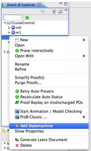
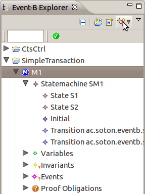
To start the modelling all you have to do is to select a machine in the Event-B Navigator that you would like to extend with state machines and right click to get the Context Menu. Then select Add Statemachine from the context menu. An input dialog will appear asking you to name the new state machine. After that you should see the new state machine appear in the contents of the machine in the navigator. Double click on the statemachine in the navigator in order to open the statemachine diagram editor. In addition, there are Open and Delete actions available for state machine in the context menu of the navigator. These allow to open a state machine in editor (shortcut is double-click) and delete a state machine (shortcut is Delete key).
Diagram Editor

To edit a state machine in the diagram editor you simply double-click it in the navigator. The tool creates a diagram file for you with the same name as the root state machine.
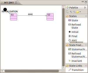
Working with the editor is straightforward. The element creation tools are available from palette, divided into three categories: States, State Features and State Links. When a diagram element is selected on canvas the Properties View shows its available properties (if you cannot find it, please go to Rodin's menu Window > Show View > Properties). This view allows you to modify important features of each diagram element that will affect its translation.
Diagram editing is possible by using either a single editor, as state machines support unbounded level of nesting, or multiple editors - by opening each specific state machine in a separate editor (select Open Diagram from context menu of a nested state machine after right-clicking it). As nesting depth of state machines and number of states grows and the model becomes large this can be a useful feature.
After a state machine is complete it can be validated to make sure it has no semantic errors and translated to Event-B. When translated, it can be animated with ProB.
Toolbar
iUML-B contributes four toolbar buttons which perform the following actions:
- Validate - Runs the validator to check that the state-machine model is well-formed
- Translate to Event-B - Generates the Event-B that the State-machine represents. (Automatically runs the Validator first)
- Start Animation - Animates the state-machine diagram (using ProB)
- Stop Animation - Stops the state-machine animation and returns to the Event-B editing perspective
Diagram Elements
The diagram allows to create the following State elements:
- State
- Initial
- Final
- Junction
- Fork/Join
- Any
A state can have nested state machines, added from State Features (also called parallel (or orthogonal) regions). A state may have invariants (or theorems) which are defined as Event-B predicates. States can have transitions from one to another, created from State Links.
Transition Properties
A transition can be endowed with any of the features that are normally contained in events (i.e. parameters, witnesses, guards, actions). These features are added in the properties view when the transition is selected. They will be copied into the elaborated events when the state-machine is translated. Hence, although the state-machines are envisioned as ancilliary to a regular Event-B model, all modelling can be done from the diagram if so desired. [Note that only guards may be added to transition segments that target a junction (see below)].
Junctions
A junction pseudo state is available from the diagram palette. Incoming transition segments to a junction generate a disjunctive guard. I.e. the transition may fire from either of the incoming transition's source states. Junctions can be cascaded if required in order to build a bigger disjunction.
Junctions can also be used to split the transition path so that the incoming disjunction is contributed to all of the outgoing paths
Note: transition segments that target a junction may not elaborate events.
Forks and Joins
A fork/Join pseudo state is a available from the diagram palette. (The same pseudo state node is used for both fork and join). A fork is used so that a single transition can enter several parallel nested statemachines (which must all have the same parent state). A join is used to exit several parallel nested statemachines.
Any
An any pseudo state is a available from the diagram palette. An any state is used to represent all of the states at the same level in the state-machine. Hence a transition whose source is an any state can fire irrespective of the current state of the statemachine. Note that the semantic is the same as a transition whose source is the parent state (statemachine boundary). Hence the any state is mostly used in the root level state-machine where there is no parent state.
Lifting
A statemachine can be lifted to a set of instances so that the statemachine represents the behaviour of all of these instances. This is similar to statemachines that are owned by a Class in the classic UML-B. In fact the feature will be used for this purpose when iUML-B class diagrams are available. The generated Event-B is lifted by adding an extra parameter to each elaborated event in order to represent the contextual instance. The name of this parameter can be specified for the state-machine. The instance set and the self-name are both set in the properties view for the state-machine. [Note that currently instances must be constants or carrier sets, variable instance sets are not yet supported].
Semantics
The semantics of Event-B state machines differ from those of UML. Like Event-B, UML-B semantics are based on the underlying concept of spontaneous atomic guarded actions that change the state of the variables. Comparing with other commonly used semantics such as UML, UML-B has no concept of external events that may trigger transitions, no ability whereby one transition may invoke another and, as there is no so-called `big-step', terms such as `run to completion' have no meaning. (All these things can be, and often are, modelled explicitly when required by constructing suitable control variables and guards).
State machines, states and transitions are integrated in Event-B machine and generate new elements in that machine upon translation:
- States translate into boolean-typed variables (variable and type invariant)
- State machines and states translate to their relationship invariants such as substate and partitioning invariant
- Transitions and states translate to event guards and actions that describe state change behaviour
While state machines and states are not related to Event-B, for transitions it is necessary to know the events to which new guards and actions will be added. Thus a transition has an attribute called elaboration that links it to Event-B event. The relationship between two is rather flexible - a single transition can elaborate multiple events, and at the same time a single event can be elaborated by multiple transitions (you must be careful though not to misuse this feature).
State invariants: Adding an invariant to a state will be interpreted in terms of Event-B as adding an invariant on state variable's value. State invariants are defined as Event-B predicates.
Validation
There are some semantic rules that must be obeyed in order for a state machine model to be valid and translatable to Event-B. These rules are implemented in the validation framework and are checked either when validation is called explicitly from context menu, or before the translation. Note that the set of rules is currently not complete thus not guaranteeing full correctness of the model.

Rules: [NEEDS UPDATING]
- Transition cannot go to initial state
- Transition cannot go from final state
- Transition cannot go directly from initial to final state
- Transition should elaborate an event if
- it is on the root state machine (its source/target belongs to root)
- it is in nested state machine and not initial or final (its source/target is initial or final state)
- Initial state should have outgoing transitions
- Final state should have incoming transitions
- Root state machine must have an initial state
- State machine can only have one initial state
- State machine can only have one final state
- State machine must have an initial state if
- its parent state has incoming transitions
- it has outgoing local transitions (going from a state to parent state or ANY state)
- Concrete state cannot contain refined state machines
- Concrete state machine cannot have refined states
- Refined state machine cannot have concrete states
Not all the rules are strict i.e. violation of certain rules is not considered as error as it doesn't cause translation problems, but keeping a model semantically correct means everything will be translated as intended.
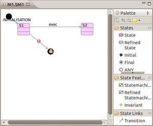
The diagram editor, as mentioned, has two ways of checking the diagram model against these rules: selecting Validate from diagram context menu or running a translation. After validation completes, it produces feedback in the form of a dialog, telling whether model is valid or has errors. The elements that violate specific rules are marked with error/warning markers, which are listed in Rodin Problems view, as well as displayed on the diagram.
Known Problems
Implicit Context extends chain becomes broken. This only applies when using the Enumerated Translation which generates an implicit context to define the enumeration set of states]. If you refine a machine containing a State-Machine without translating the refined statemachine (i.e. because your refinement didn't alter the statemachine) then subsequent refinements that do alter the statemachine introduce errors because the link to the abstract implicit context is not maintained. A work-around is to translate the statemachine of the middle refinement even though you didn’t change the statemachine. This will create an empty context to maintain the chain. Alternatively you can manually edit the extends of the implicit context in the refined level to link to the abstract implicit context. However, you can only do this using the Rose editor's Advanced tab because the generated implicit context is read-only to other editors.