Flows
The Flow plug in is a Rodin Platform extension assisting in the formulation of verification conditions related to the dynamic properties of a model, i.e., event ordering and enabledness conditions. A visual notation is used to define graph-like structures that are translated into Event-B theorems (for efficiency reasons, these appear as machine proof obligations). The tool simplifies a number of routine tasks such as writing and maintaining deadlock-freedom and relative deadlock freedom proof obligations. Its core functionality is concerned with the verification of the feasibility of use case scenarious: checking that certain event paths are feasible for a given model.

Flow diagram
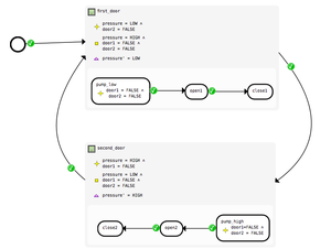
The nodes of a flow diagram are events, possibly constrained with additional predicates; its edges are event relations. There are three kinds of event relations - enabling, disabling, feasibility. The event relations state the relationship between the after-state of one event and the enabling condition of the other. A flow diagram should not be confused with a state diagram or a workflow graph. The only effect of a flow diagram is the generation of additional verification; it has no behavioral semantics and does not constrain machine behaviour.
Enabling relation
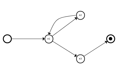
The enabling relation expresses that an event may follow some other event. More precisely, it requires that the guard of the event at the target of the relation edge is enabled after the execution of the event at the source of the edge. It is not guaranteed that the target event is executed immediately or eventually after the source event. The interference from other events may temporarily or permanently disable the target event even though it was momentarily enabled in the after-state of the first event. Below is an example of a flow diagram using the enabling relation.

Circle denotes the initialisation event; circle with a block dot is an implicit termination (or deadlock) event. The latter is defined as event with no actions and a guard formed by negating of the disjunction of the guards of all the model events (not including skip, initialisation and the termination events).
When for a node there is more than one outgoing relation of a given kind it is enough to satisfy any one of the relations. For the enabling relation, this expresses the internal choice on event firings. There are annotations, discussed further, overriding this interpretation.
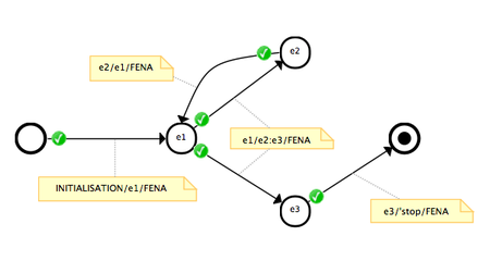
Sample diagram given above defines four theorems. There is a theorem stating that event e1 is enabled right after the initialisation (the proof obligation name is INITIALISATION/e1/FENA where the suffix FENA stands for Flow ENABledness proof obligations; this suffix is always used with enabling relation) a theorem showing that e1 enables e2 or e3 or both (the proof obligation name is e1/e2:e3/FENA and reads "after e1, e2 or e3 is enabled"; a theorem showing that after 'e3' the system terminates and, finally, a theorem for the enabledness of e1 after the execution of e2. The following is an screenshot from the tool showing the annotated diagram and proof status. Proof statuses are updated along with the progress of the Rodin builder and provers and thus there will be always some delays between saving a diagram and proof status update.

A double-click on edge would automatically open the relevant proof obligation in the interactive prover.
Disabling relation
The disabling relation is the opposite of the enabling relation: it requires that the target event is not enabled after the execution of a source event.
Update site
Use the following update site to install and update the plug in.
http://iliasov.org/usecase