Development of a Heating Controller System: Difference between revisions
imported>Reza |
imported>Reza |
||
| Line 87: | Line 87: | ||
[[Image:Decomp1.jpg|center]] | [[Image:Decomp1.jpg|center]] | ||
The environment machine includes all the physical parts that the system we are intended to build is interacting with. These include buttons, sensors, actuators and their related behaviours. In addition to these the environment machine has to include the synchronisation mechanism between the physical | The environment machine includes all the physical parts that the system we are intended to build is interacting with. These include buttons, sensors, actuators and their related behaviours. In addition to these the environment machine has to include the synchronisation mechanism between the physical elements and our system. | ||
===Second level decomposition=== | ===Second level decomposition=== | ||
In this stage we decompose the controller to some tasks that communicating through a shared object. Note that tasks still are able to communicate with the environment directly. | In this stage we decompose the controller to some tasks that communicating through a shared object. Note that tasks still are able to communicate with the environment directly. | ||
[[Image:Decomp2.jpg|center]] | [[Image:Decomp2.jpg|center]] | ||
Revision as of 15:15, 3 May 2011
Introduction
This section describes an Event-B development of a simple heating controller. This is a first case study that covers the entire development process; starting from a system specification and ending up in an implementation in the Ada programing language. The development process starts with an abstract specification followed by two successive refinements before decomposing the model to two separate sub-models. The refinement process continues after the first decomposition in order to arrive at a concrete level suitable for implementation. This allows us to devise an appropriate tasking structure that needed by the code generation plug-in. The outcomes of the second decomposition are a number of tasking machines plus a specific type of machine for representing protected shared data. This protected shared data facilitating communications between tasking machines. Then we illustrate how using the code generation plug-in a concurrent Ada implementation is generated. The overall aim of this case study is to put in practice the recommended methodological aspects of Event-B, particularly those aspects of modelling concerned with decomposition and code generation.
System Architecture
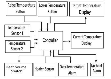
In the System Architecture diagram an overview of the Heating Controller and its related components are presented. The controller in the middle of the diagram communicates inputs and outputs parameters with its surrounding components. At the top there are two buttons that allow the user to increase/decrease Target Temperature. The target temperature periodically will be sent by the controller to the related display to be shown to the outside world.
The controller uses two Temperature Sensors to poll the environment temperature. The average of the values read from these two sensors is calculated and displayed by the controller on the Current Temperature Display. If the current temperature is lower than the target temperature, the controller will turn on the heater source using Heat Source Switch, otherwise this switch will be turned off by the controller. The status of the heater itself also will be monitored through the Heater Sensor. If due to some faults the heater is not working properly, the controller will activate either of Over-temperature Alarm or No-heat Alarm
Main Functionaly of the System
- Provideing interface to adjust Target Temperature
- Displaying new Target Temperature
- Sensing Current Temperature
- Displaying Current Temperature
- Power on/off the Heater
- Sensing the Heater Status
- Activating/Deactivating No-Heat Alarm
- Activating/Deactivating Over-Heat Alarm
| Interfaces | Types | Definitions |
|---|---|---|
| Increase/Decrease Target Temp. Buttons | Boolean | True when buttons are pressed |
| Temperature Sensors | Integer | Temperature in degrees Celsius |
| Heater Sensors | Boolean | True when heater is at working temperature, False otherwise |
| Heat Source Switch | Boolean | True when activated, False otherwise |
| No-heat Alarm | Boolean | True when activated, False otherwise |
| Over-temperature Alarm | Boolean | True when activated, False otherwise |
| Current temperature Display | Integer | Average temperature value in degrees Celsius |
| Target temperature | Integer | Target temperature value in degrees Celsius |
An Overview of the System Development
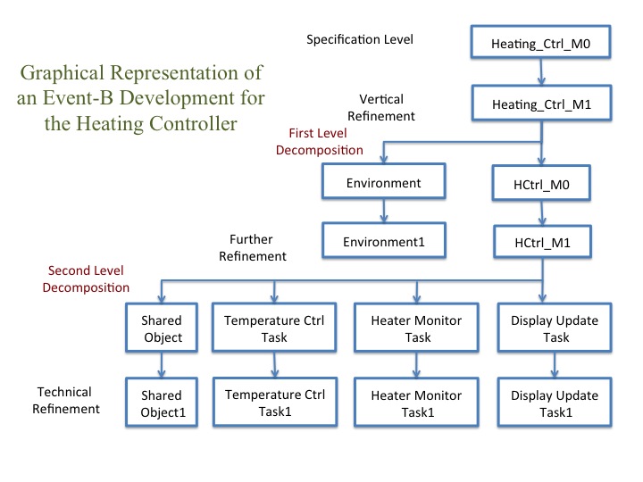
Before starting with the discussion of the Event-B models for the Heater Controller it is useful to provide an overview of our development approach. In this section we demonstrate this with a diagram. Starting from the top level of the diagram, it shows the most abstract model of the system or as it know as the system specification. In this stage we have specified the main system’s functionality. This includes events for modelling increase/decrease target temperature, polling environment temperature using two available sensors, calculating current temperature, turning on/off the heat source, and finally activating or deactivating two deferent alarms should it deemed to be necessary by the controller. Events in this stage are deliberately simple to achieve maximum comprehensibility. Events ordering and sequencing is introduced in the later stages.

In the first refinement level we introduce sensing and actuation which are considered as design steps. Here sensing involves polling the state of increase/decrease buttons, environment sensors and the heater sensor. Actuation concerns with updating target and current temperature displays with latest values, as well as sending outcomes of controller decisions to appropriate actuators such as hear on/off and different alarms.
System Decomposition
As illustrated in the system development diagram we decompose our model in two stages. In the first stage we separate the controller, the part of the system that should be implemented, from its surrounding environment. The second stage of decomposition is concerned with the tasking structure of the implementable system. This an open issue for the designer and it is based on his/her personal choice as well as targeted platform and possible options available to him/her.
First level decomposition
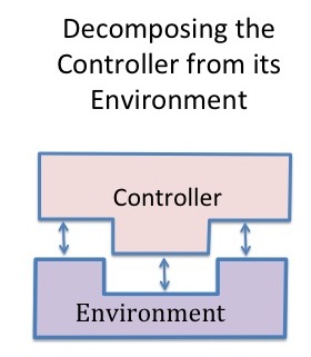
In Event-B usually we start modelling with specifying the whole system as a closed system. This includes the system that we are intending to develop plus its surrounding environment. Therefore when our model of the system becomes big and complex it is reasonable to separate the actual system from its environment. Hence in the first stage of decomposition we decompose our model to two parts, namely the controller and the environment.

The environment machine includes all the physical parts that the system we are intended to build is interacting with. These include buttons, sensors, actuators and their related behaviours. In addition to these the environment machine has to include the synchronisation mechanism between the physical elements and our system.
Second level decomposition
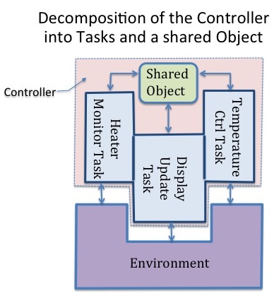
In this stage we decompose the controller to some tasks that communicating through a shared object. Note that tasks still are able to communicate with the environment directly.

