Modularisation Plug-in Tutorial: Difference between revisions
imported>Alexili No edit summary |
imported>Alexili mNo edit summary |
||
| Line 25: | Line 25: | ||
The following diagram shows the stages of the system operation that let a user to get outside starting in the inside area. | The following diagram shows the stages of the system operation that let a user to get outside starting in the inside area. | ||
[[Image:SluiceControllerSolution.png| | [[Image:SluiceControllerSolution.png|500px]] | ||
The shaded rectagles denote a pressure level, high pressure area corresponds to a higher rectangle. The "u" label marks the current position of a system user. Initially, a user is inside and the sluice pressure is levelled with the outside pressure. Before the door connecting to the sluice is opened, the pressure is decreased to level it with the inside pressure. Once the door is open, the user moves in, the door is sealed again. Finally, the sluice pressure is set to match the outside pressure and the door leading may be safely opened. | The shaded rectagles denote a pressure level, high pressure area corresponds to a higher rectangle. The "u" label marks the current position of a system user. Initially, a user is inside and the sluice pressure is levelled with the outside pressure. Before the door connecting to the sluice is opened, the pressure is decreased to level it with the inside pressure. Once the door is open, the user moves in, the door is sealed again. Finally, the sluice pressure is set to match the outside pressure and the door leading may be safely opened. | ||
Revision as of 13:04, 22 October 2009
Modularisation Plug-in Tutorial
Go to the plug-in description page.
The tutorial illustrates the use of the modularisation plug-in in an Event-B development. The example used is rather small scale but it still demonstrates some basic principles of introducing modules during the development process.
Sluice Control Example
The example is a sluice with two doors connecting areas with dramatically different pressures. The pressure difference makes it unsafe to open a door unless the pressure is leveled between the areas connected by the door. The purpose of the system is to adjust the pressure in the sluice area and control the door locks to allow a user to get safely inside to outside. Such system can be deployed, for example, on a submarine to allow divers to get out while submerged.
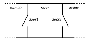
The system parts are two doors that can be operated independently of each other and a pressure controller that allows the change of pressure in the sluice area. The following is a schematic depiction of the system.
The system is summarised with the following set of requirements:
- the system allows a user to get inside or outside by leveling pressure between room and a destination
- the system has three locations - outside, sluice and inside
- the system has two doors - door1, connecting outside and sluice, and door2, connecting sluice and inside;
- there is a device to change pressure in sluice;
- a door may be opened only if the pressures in the locations it connects is equalised;
- at most one door is open at any moment;
- the pressure can only be switched on when the doors are closed.
Requirements 1-4 characterise the system by stating its goal and its major parts. The last three characterise the system behaviour. More precisely, they are the safety properties of the system.
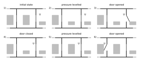
The following diagram shows the stages of the system operation that let a user to get outside starting in the inside area.
The shaded rectagles denote a pressure level, high pressure area corresponds to a higher rectangle. The "u" label marks the current position of a system user. Initially, a user is inside and the sluice pressure is levelled with the outside pressure. Before the door connecting to the sluice is opened, the pressure is decreased to level it with the inside pressure. Once the door is open, the user moves in, the door is sealed again. Finally, the sluice pressure is set to match the outside pressure and the door leading may be safely opened.

